

Quizlet How Is Data From Sensors Onboard The Landsat System Transferred To Earthã¢â‚¬â„¢s Surface?
- Definitions
- History & Significance of Landsat in GIS&T
- Remotely Sensed Data Characteristics
- Sensors onboard Landsat Satellites
- Landsat Information Format
i. Definitions
Reflected and emitted lite: When light interacts with objects it can exist a) transmitted, b) captivated, or c) reflected. Objects that absorb light will emit the free energy afterwards. The reflected and emitted light forms the ground of remote sensing.
Passive sensor: An electronic device or instrument that records the intensity of light reflected or emitted from objects. The source of the incident calorie-free is external to the sensor (e.g., the sun).
Pixel: Stands for picture-element and is the smallest spatial unit of measurement recorded by the sensor.
Multispectral data: Spectral data acquired in more than iii wavelength bands of the electromagnetic spectrum. Data recorded in each region is referred as a spectral ring or channel.
Polar orbiting satellites: Satellites that orbit the world along a path goes over, or close to, both poles.
Sunday synchronous satellites: A course of polar orbiting satellites where each repeat orbit of the satellite passes a particular ground location at the same local time of the day. Data collected by these satellites are well suited for analyzing changes over time.
Scene: Equally satellites orbit along a path, the sensors scan the terrain below and collect data. These information are divided into individual frames called scenes. Each scene is identified by its unique path (Northward-Southward) and row (Eastward-West) numbers.
two. History & Significance of Landsat in GIS&T
Remotely sensed data caused past NASA/USGS Landsat serial of satellites constitute the longest collection of Earth Ascertainment (EO) imagery information. The first satellite was built and launched by the United states Department of Interior, NASA, and the United states of america Section of Agronomics in 1972 as Earth Resources Applied science Satellite (ERTS-i) and was later renamed as Landsat 1 (Figure 1). Seven satellites take been launched since then, however Landsat 6 failed to reach its orbit. Landsat five, launched in 1984, collected information for 28 years and x months, and made an entry in the Guinness World Volume every bit the "Longest Operating Earth Observation Satellite". Landsat 7 and 8 are currently operational and together they collect more than 1500 scenes every day. However, there are gaps in the images collected past Landsat 7 since May 2003, due to a mechanical failure (For more details, see Department four.iv). The next satellite in the sequence, Landsat 9, is scheduled for launch in 2021.
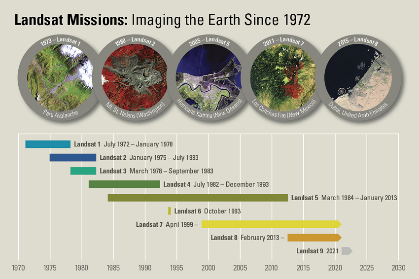
Figure ane. A timeline history of Landsat satellite missions. Source: US Geological Survey.
After the United States Geological Survey (USGS) opened the entire Landsat annal for no-price use, involvement in these EO data have increased several folds (Zhu et al., 2019). Numerous studies accept combined images acquired past 1 or more Landsat satellites to narrate earth surface features and their changes from local (Cai et al., 2018) to global (Hansen et al., 2013) scales. Landsat data are used for countless number of applications in agriculture, forestry, grassland, rangeland, disaster response, hydrology, and land cover/use and alter analyses (Sivanpillai, Jones & Lamp 2017; Young et al., 2017). Landsat images are also used as a visual backdrop in many GIS applications. Information derived by manual estimation or digitally candy images are integrated with existing data in geospatial modeling applications.
iii. Remotely Sensed Data Characteristics
Landsat images nerveless over the decades accept varied due to differences in the onboard sensors (section three) used for collecting them. Landsat imagery data are characterized past the following four resolutions: a) spatial, b) spectral, c) radiometric, and d) temporal. Spatial resolution corresponds to the size of the pixel on the ground (e.one thousand., 15 ten 15 k). Spectral resolution refers to width of the regions in the electromagnetic spectrum in which data are acquired. Radiometric resolution corresponds to the range of values betwixt minimum and maximum, which are used for distinguishing the brightness values. Since these values are digitally stored, radiometric resolution is denoted as 2n, where northward corresponds to the number of bits. For example, when due north = half dozen bits, 64 levels of brightness values that tin be stored that range from 0 (minimum) to 63 (maximum). As n increases more subtle differences in effulgence values can exist distinguished and stored. Temporal resolution refers to the time lapsed between any ii sequent acquisitions. This is too referred as the revisit time of the satellite. For more data on this topic, come acrossNature of Multispectral Paradigm Information.
four. Sensors Onboard Landsat ane-eight Satellites
Over the decades, the passive sensors onboard the Landsat satellites accept evolved by capitalizing on advances in optics, electronics, and communication technology. Owing to these advances, the blazon and capabilities of sensors take as well changed in newer Landsat missions.
4.1 Render Axle Vidicon
The render bean vidicon (RBV) was similar to a Tv camera and was designed as the primary instrument for acquiring photogrammetric quality images from infinite. Initially, it was assumed that these space-based images would be like to the aeriform motion-picture show-based cameras that were widely used in photogrammetric applications. The RBV on Landsat 1 and ii had three contained cameras that acquired in images in green, ruby-red, and near infrared regions. Shutters in each camera simultaneously opened and recorded the spectral data for a geographic region. These three independent images that were slightly first because they were acquired by contained cameras were 'co-registered' to generate a false-color Landsat scene. However, the images acquired by RBV had high spatial distortions, and the sensor experienced some technical difficulties. Therefore, the focus shifted to the Multi-Spectral Scanner (department 4.two) arrangement.
The RBV sensor on Landsat two was identical to the one in the first satellite just was seldom used. Landsat three carried a RBV with two cameras capable of acquiring data in broad spectral regions (greenish to almost infrared), and like its predecessors, its data was also rarely used. Additional details about RBV data tin be establish in the USGS RBV - Movie only page (USGS).
4.2 Multi-Spectral Scanner
Multi-Spectral Scanner (MSS) was an across-track sensor that acquired spectral data for ane pixel at a time unlike RBV that performed similar cameras. Beyond-track or whisk broom sensors consist of a mirror that scan the earth surface perpendicular to the motion of the satellite. Each scan would issue in row(s) of pixels and as the satellite moved forrard the sensor would collect the side by side rows.
A numeric value was assigned to the pixel based on the intensity of incoming radiation for a given wavelength (Campbell, 2007). Scanners build a line of pixels for the width of 185 km referred every bit the swath of the MSS image. MSS had 24 carve up detectors that were capable of scanning vi lines at a time in iv spectral (green, red, and two infrared) bands.
Spectral data collected by scanning devices produce an image in an electronic device by displaying ane pixel at a time. MSS sensors on Landsat 1-three had a revisit time of 18 days. When the orbital meridian of Landsat 4 and 5 was lowered to 705 km, the revisit fourth dimension reduced to 16 days. Other characteristics of MSS data are summarized in Table one.
four.3 Thematic Mapper
Thematic Mapper (TM) was similar to the earlier MSS but collected data in 7 spectral regions and as well at relatively higher spatial resolution (thirty m). These improvements were aimed at collecting higher quality data for better differentiating the earth surface features. The radiometric resolution of TM was also higher (8 bits) which means the incoming spectral radiation can be separated to 256 brightness levels. Other characteristics of TM data are summarized in Table (1). The swath of each TM scene was set at 185 km matching the earlier MSS scenes. TM instruments were part of Landsat 4 and 5 missions.
4.4 Enhanced Thematic Mapper Plus
Enhanced Thematic Mapper Plus (ETM+) scanning instrument on Landsat 7 is similar to TM in terms of its radiometric and temporal resolutions. The spatial resolution of the thermal infrared band was increased to sixty m. A new panchromatic band with fifteen m was added to the ETM+ (Table 1). The swath of each ETM+ scene was kept at 185 km to friction match the earlier Landsat MSS and TM scenes. Other hallmarks of ETM+ was its improved radiometric scale, better filter and detector technology which increased the performance and accuracy.
ETM+ suffered a setback on May 31, 2003 when the Scan Line Corrector (SLC) failed. The SLC compensated for the satellite'southward frontward motion of the across-runway scanner and its failure resulted in gaps in the scene. The middle 20% of each scene (in the north-south direction) was non impacted by SLC failure and gaps of missing scan lines appear on either side of the scene (in the e-west direction).
4.5 Operational Land Imager
Operational Land Imager (OLI) onboard Landsat viii is similar to TM and ETM+ in terms of the orbital characteristics, swath (185 km), and spatial resolution. The radiometric resolution was improved to 12 bits in order to capture finer details in brightness values and to improve the signal-to-noise ratio. 2 new bands, coastal bluish (0.43 - 0.45 µm) and cirrus (1.36 - 1.38 µm), were added. Data collected in cirrus band are used for automatic cloud cover assessments. Unlike, TM and ETM+, OLI does not collect thermal data since a separate instrument was added to Landsat 8 mission (section iv.6). Other characteristics of OLI sensor are summarized in Tabular array (one).
OLI is an along track or push broom scanner where the browse lines are parallel to the movement of the satellite. This was a major modify made to the newest sensor compared to its predecessors.
4.6 Thermal Infrared Sensor
Thermal Infrared Sensor (TIRS) onboard Landsat 8 is a standalone, forth track or push broom scanning musical instrument, which collects data in two longwave thermal infrared wavebands (Table one). In contrast the TM and ETM+ sensors recorded a single measurement in the same region. Two bands of thermal data provide the potential for improved estimates of surface temperature, compared to a single band. However, ghosting in the TRS second band reduced the effectiveness of this approach. TIRS and OLI (department 4.vi) simultaneously collect data.
| Resolution | |||||
| Sensor | Satellite # | Spatial (grand) | Radiometric | Temporal | Spectral |
| MSS | L01-05 | 80a | 6 bits | eighteen/xvi daysb |
|
| TM | L04-05 | xxxc/120d | 8 bits | xvi days |
|
| ETM+ | L06e-07 | xxxc/60f/fifteenthousand | 12 $.25 | 16 days |
|
| OLI | L08 | 30c/15g | 12 bits | 16 days |
|
| TIRS | L08 | 100 | 12 bites | sixteen days |
|
Notes:
a Spatial resolution of MSS data were 80 m but they are distributed every bit 60 m pixels.
b Temporal resolution or revisit time of Landsat ane-3 was eighteen days, and for Landsat 4-5 was 16 days.
c Spatial resolution of the Multispectral bands in Landsat five, 7 and eight is 30 grand.
d Spatial resolution of the Thermal band in Landsat 4 and 5 was 120 meters.
eastward Landsat half-dozen failed to reach orbit.
f Spatial resolution of the Thermal band in Landsat 7 is 60 meters.
1000 Spatial resolution of the Panchromatic band in Landsat seven and 8 is 15 meters.
Spectral data from MSS, TM, ETM+, and OLI are available every bit digital numbers, at sensor spectral radiance, at sensor reflectance, and surface reflectance (Young et al., 2017). The Landsat data archive can exist queried and downloaded from the USGS EarthExplorer website (https://earthexplorer.usgs.gov) or from other private entities. These conversions are completed as part of information pre-processing. The USGS uses specific product data such every bit Level 0, Level 1G, and Level 1T to identify the type and level of pre-processing completed for a Landsat scene. Since USGS opened the archive at no-price, Landsat information tin can be accessed from USGS and other sources as Google Earth Engine, and Amazon Spider web Services. If users download information from more than one source, it is imperative to pay close attention to the type of pre-processing completed to minimize erroneous results.
v. Landsat Information Format
Landsat images are available as scenes (Figure 2) and the swath width of each scene is 185 km (distance in the east-west management). The altitude in the along-track management (north-due south) ranges between 170 km and 180 km for different sensors. Landsat scenes are identified by their unique path/row numbers associated with the Worldwide Reference Arrangement (WRS). Scenes from Landsat 1-3 were part of the WRS-1, whereas the rest of the scenes starting from Landsat 4 are office of the WRS-2.
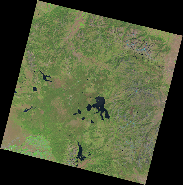
Figure 2. A Landsat scene (Worldwide Reference Organisation-ii Path 38, Row 29) acquired on Baronial xv, 2020 covering Yellowstone National Park (Wyo. USA). Yellowstone Lake is in the middle and Jackson Lake is directly south in the scene acquired by the Operational Land Imager onboard Landsat viii. Source: US Geological Survey.
v.1 Collections Level Data
Starting in 2016, USGS reprocessed the unabridged Landsat archive to common accuracy standards and organized them equally Collection Level Data. Inside a collection, Landsat scenes are assigned to Tiers based on quality and level of processing. Scenes that are minimally processed are placed in the tier named Existent Time (RT). These scenes provide rapid data for applications such every bit disaster response. Side by side, scenes are processed for terrain effects and inter-calibrated with data from other Landsat sensors. Scenes with highest precision and terrain corrected data with ≤ 12-meter RMS error are placed in Tier 1 (T1). Scenes that do not run across this stringent quality are placed in Tier ii (T2). Thus, users can make up one's mind the quality and analyze whatever number of scenes in the archive irrespective of the sensor that acquired a detail image. Users can obtain Landsat imagery that are part of Collection 1 as Digital Numbers (DNs), at sensor reflectance, and surface reflectance values.
In Dec 2020, USGS reprocessed and released Collection 2 Landsat information. Collection 2 scenes take increased geolocation accuracy which improves the interoperability of Landsat data over the unabridged annal. In Collection 2, simply DNs and surface reflectance values are provided; at sensor reflectance, if needed, has to be calculated by users on their own. Each new drove comprises images with college quality. Hence users should not combine Landsat scenes from dissimilar collections for whatever applications.
The level of processing completed for any Landsat scene tin can be derived from its ID. For example, based on the following ID, 1 can determine the following information:
LC08_L1TP_038029_20200815_20200919_02_T1
Fifty: Landsat (Abiding)
C: Sensor (C: OLI/TIRS)
08: Satellite number (08)
L1TP: Processing level (Level 1 Terrain Precession)
038029: WRS2 Path 38; Row 29
20200815: Acquisition date (YYYYMMDD)
20200919: Processing date (YYYYMMDD)
02: Drove number
T1: Tier level (T1 highest quality)
NOTES:
- Options for sensor: C: OLI/TRIS O: OLI; T: TIRS; E: ETM+; T: TM; M: MSS
- Options for satellite number: 01, 02, 03, 04, 05, 07, 08, etc.
- Options for Processing level: L1TP, L1GT, L1GS
- Options for Drove number: 01, 02
- Options for Tier: RT, T1, T2
Within a drove, if whatever Landsat scene is reprocessed it will be reflected with a new Processing date. Users should check the archive for any updates prior to using Landsat scene(s) downloaded at an earlier engagement.
5.ii Analysis Ready Data
In 2018, USGS released Analysis Ready Information (ARD) for the Us based on a tiled grid reference organisation instead of path/row format. Each Landsat tile consists of 5000 ten 5000 pixels and is smaller than a scene (Effigy iii) and are identified by a unique horizontal-vertical number.
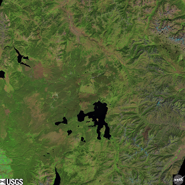
Figure 3. A Landsat tile grid (Horizontal nine; Vertical v) generated from the scene acquired on August 15, 2020 covering the Yellowstone National Park (Wyo. Usa). There are 5000 x 5000 pixels in each tile filigree. Source: US Geological Survey.
Landsat ARD tiles for the US contain Top of Atmosphere (TA) reflectance, acme of atmosphere Brightness Temperature (BT), Surface Reflectance (SR), and quality assessment information. ARD tiles can exist directly used for time-series analyses thus reducing the time to download and pre-process big number of Landsat scenes.

Quizlet How Is Data From Sensors Onboard The Landsat System Transferred To Earthã¢â‚¬â„¢s Surface?,
Source: https://gistbok.ucgis.org/bok-topics/2021-quarter-03/landsat
Posted by: rothblead1998.blogspot.com
0 Response to "Quizlet How Is Data From Sensors Onboard The Landsat System Transferred To Earthã¢â‚¬â„¢s Surface?"
Post a Comment